Research Project Categories
Hydrofoil Optimization:
The objective of this example is to maximize the minimum pressure over a 3D hydrofoil at a fixed lift. This type of objective function is often encountered in hydrodynamics, where cavitation is always a concern. The evolution of the hydrofoil surface through the design cycles is and the superposition of the optimum profiles can be observed here.


The initial and final pressure distribution over the hydrofoil surface are presented below respectively, and the evolution of the minimum pressure coefficient is shown at the bottom.


The lift variation at the end of the optimization cycles was negligible.
Ship Hull Optimization:
The objective of this example is to minimize the wave drag of the Wigley hull presented here.

The hull surface is parameterized using an innovative pseudo-shell approach, which produces deformation modes as the ones presented here.

After eight design cycles, a 90% of wave drag reduction is obtained. A comparison between the initial hull (dashed line and bottom left figure) and final one (continuos line and bottom right figure) can be observed here.

Paper Mill Optimization:
The objective of this example is to obtain an equal flux at the three lower outflow exits of the outflow of a paper machine. The design parameters are the 4 B-Spline points of the upper surface, which are allowed to change within specified bounds. The cost function is defined as the sum of the squares of the difference between the flux at the outflows and the average flux. A gradient based search with finite difference evaluation is used to drive the optimization. The shape change obtained may be seen below, with the associated reduction in cost function.


The velocity for the initial and final shapes, as well as the pressure can be seen below.


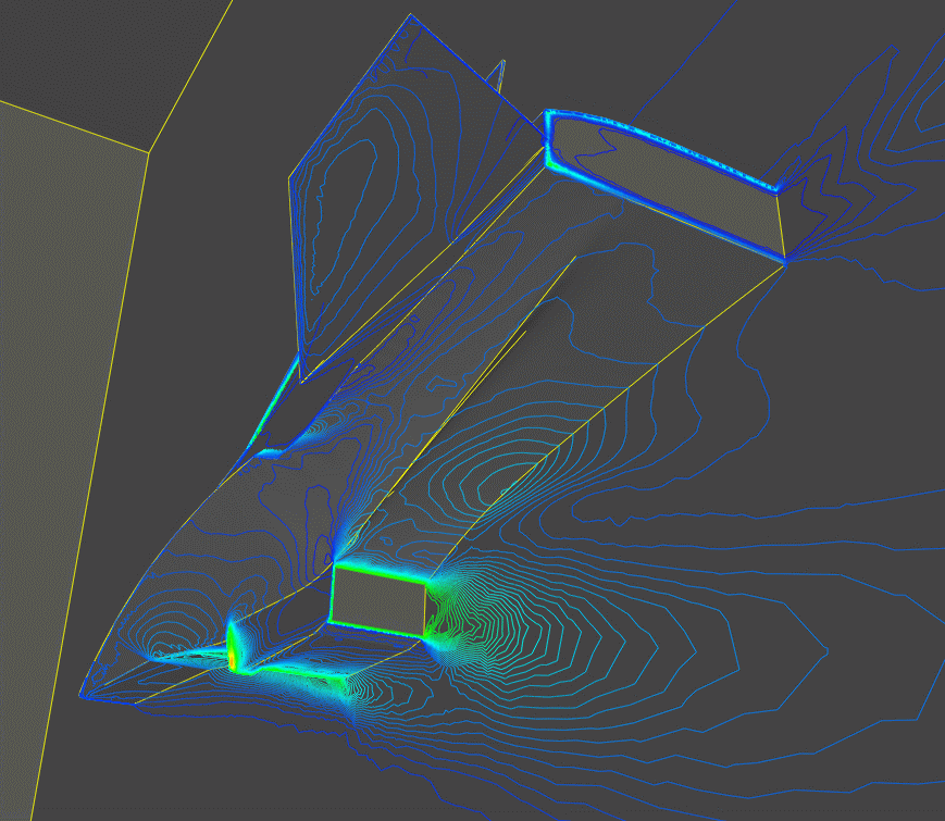
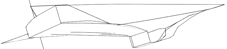
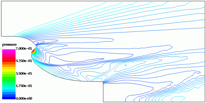
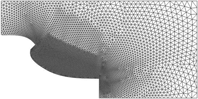
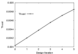
Optimization of an External Nozzle:
This example considers an external nozzle, typical of those envisioned for the X-34 airplane. There are no constraints on the shape. The objective is to maximize the thrust of the nozzle. The flow conditions were set as follows:
- Inflow (external flowfield): Ma=3.00, density=0.5, velocity=1.944, pressure=0.15, angle of attack=0.0;
- Nozzle exit: Ma=1.01, density=1.0, velocity=1.000, pressure=0.18, angle of attack=-45.0;
The mesh had approximately 51 Kpts and 267 Ktet. A gradient based optimization was performed; the gradient was obtained using an adjoint solver. The initial and final mach-numbers, pressures, and surface meshes, as well as the evolution of the shape and the thrust can be seen below.
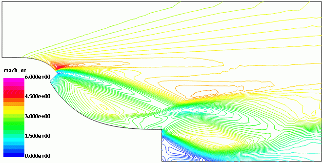
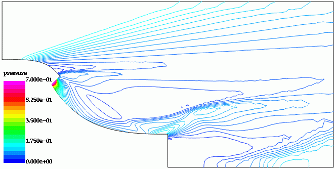
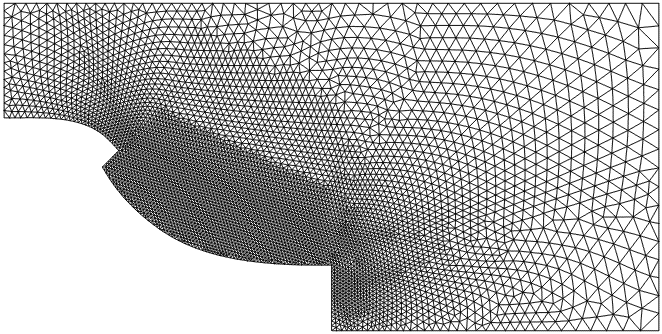
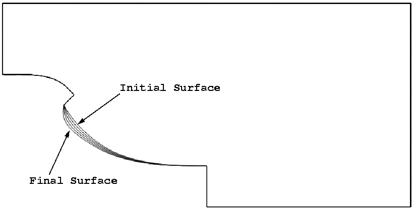
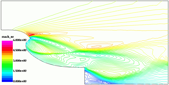
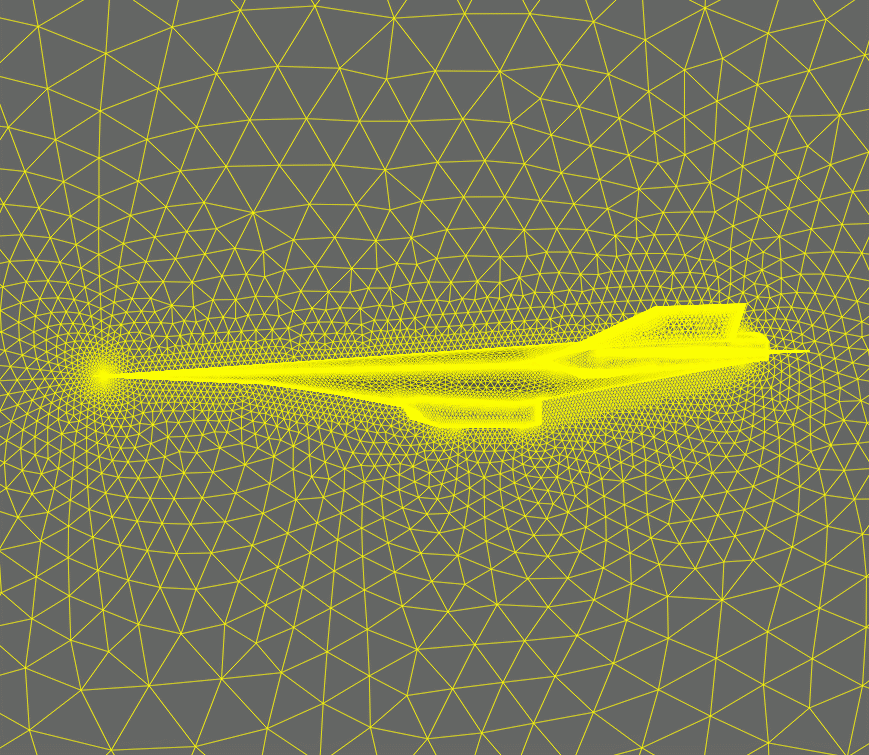
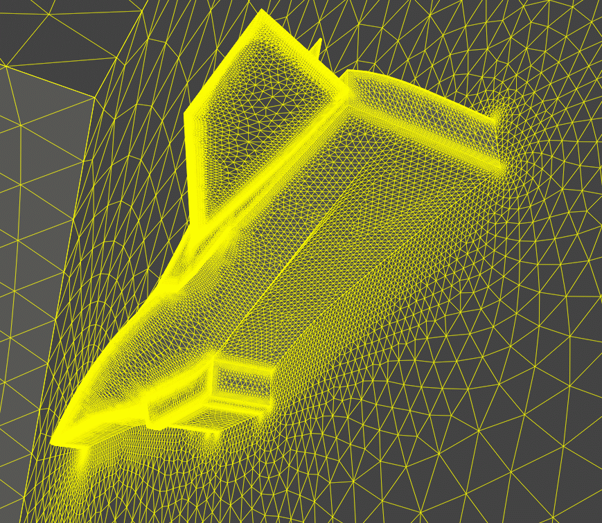
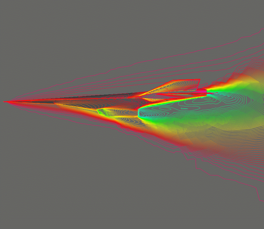
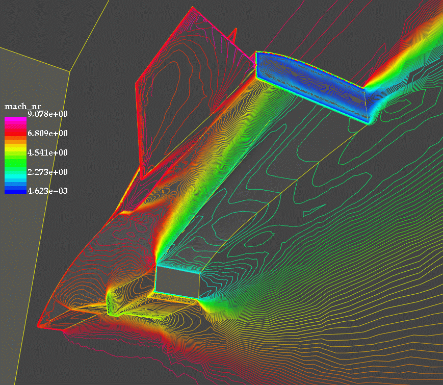
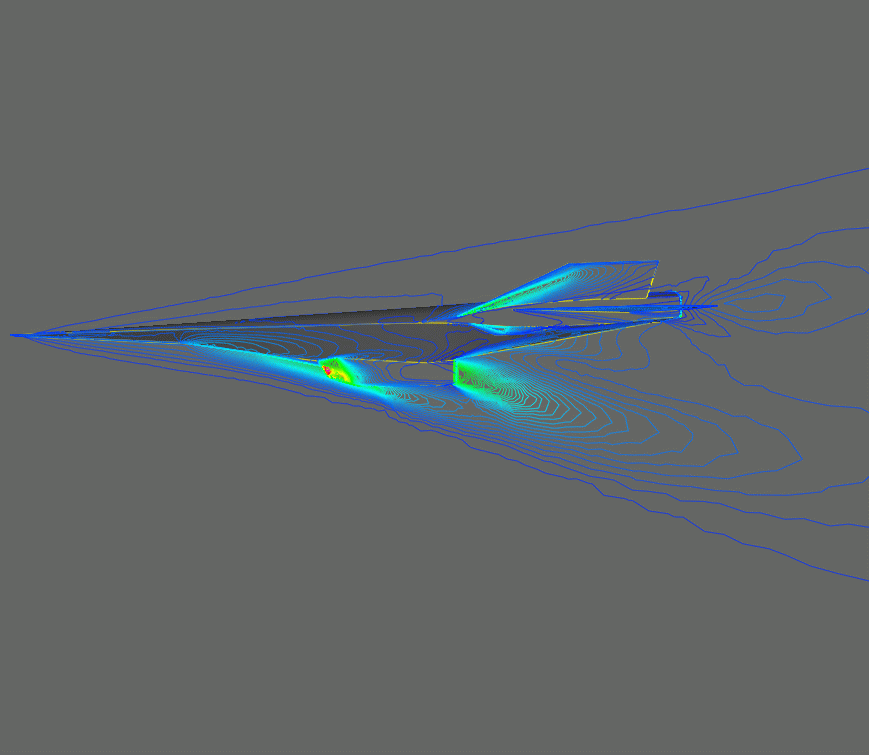
Shape Optimization for Hypersonic Flyer:
This example considers a typical hypersonic vehicle. The objective is to modify the surface behind the engine exhaust in order to maximize the thrust. There are no constraints on the shape. The flow conditions were set as follows:
- Inflow (external flowfield): Ma=8.00, density=0.004826, velocity=519.2, pressure=341.9, angle of attack=2.0;
- Nozzle exit: Ma=2.00, density=0.048260, velocity=630.0, pressure=3419.0, angle of attack=0.0;
The mesh had approximately 375 Kpts and 2 Mtets. A gradient based optimization was performed; the gradient was obtained using an adjoint solver. The initial mesh, Mach-numbers, pressures, as well as the evolution of the shape can be seen below.